 EN
EN

Core Durability Engineering: No Moving Parts, Contamination Resistance, and Thermal Stability
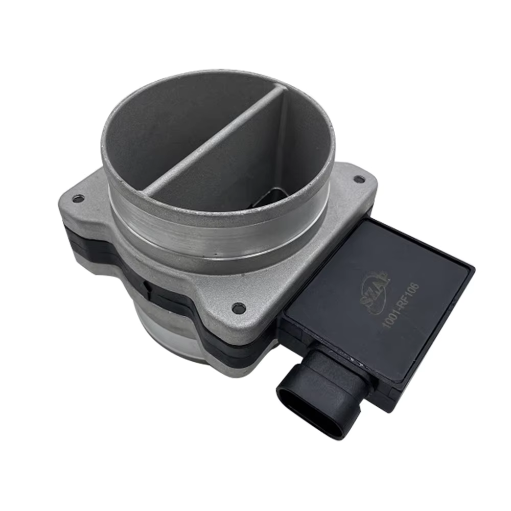
The foundation of a truly durable mass air flow sensor lies in its core engineering design. Unlike older vane-type sensors, modern hot-film or MEMS-based sensors contain no moving parts—eliminating mechanical wear, fatigue, and friction that historically caused failure after years of use. This solid-state architecture enables structural integrity to persist for over a decade, even under constant engine vibration.
Advanced contamination resistance is equally critical for preventing signal degradation in harsh under-hood environments. Leading manufacturers apply specialized conformal coatings—such as silicon nitride or polyimide—and oil-vapor-resistant barriers to shield the sensing element from oil mist, dust, and moisture. These protections prevent accuracy drift caused by fouling, a common failure mode in unprotected units.
Thermal stability is indispensable: engine bay temperatures can exceed 150°C, while cold starts may dip below −40°C. Engineering a sensor to maintain ±1% accuracy across this full range demands careful material selection—including substrates with low coefficients of thermal expansion (CTE)—and precision thermal management. The following table outlines how thermal engineering directly impacts long-term viability:
| Design Factor | Typical Standard | Impact on Sensor Durability |
|---|---|---|
| Temperature Compensation Algorithm | Active digital correction | Maintains signal linearity across temperature extremes |
| Substrate CTE Matching | Silicon-to-ceramic match | Prevents micro-cracking during thermal cycling |
| Thermal Isolation Design | Deep trench etching | Reduces heat sink effect from housing, improving response time |
| Protective Coating | Silicon nitride or polyimide | Shields the die from moisture and thermal shock |
Long-Term Signal Integrity: Drift Mitigation, EMI Immunity, and Output Consistency
Maintaining precise airflow readings over years of service requires robust signal integrity engineering. Electromagnetic interference (EMI) from ignition systems, alternators, and other vehicle electronics can distort sensitive measurement signals. High-quality sensors counteract this with EMI-shielded circuitry—typically incorporating Faraday cages—and differential sensing architectures that cancel out common-mode noise. These features ensure stable voltage or frequency output to the ECU, even in electrically noisy engine bays.
MEMS/Hot-Film Drift Compensation Techniques—Self-Calibration, Temperature-Compensated Algorithms, and Reference Element Stabilization
Sensor drift—a gradual deviation from factory calibration—is mitigated through integrated MEMS or hot-film compensation strategies. Leading designs include reference elements that provide stable baseline measurements independent of airflow. Coupled with temperature-compensated algorithms and periodic self-calibration cycles, these systems sustain accuracy within ±1% over extended service life. This multi-layered approach prevents the slow inaccuracies that manifest as poor fuel trims, elevated emissions, and reduced drivability in aging sensors.
OEM-Grade Construction vs. Aftermarket Trade-Offs for a Durable Mass Air Flow Sensor
Housing integrity, vibration-damped mounting, and oil-vapor-resistant coatings: What separates true durable MAF sensors from budget alternatives
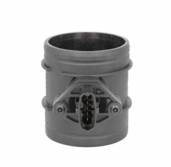
The structural foundation of a durable mass air flow sensor determines its resilience against harsh under-hood conditions. OEM-grade units use high-pressure molded thermoplastics or cast aluminum housings with seamless welds—preventing micro-cracks that allow moisture ingress in lower-tier alternatives. Integrated rubber-isolated mounting brackets absorb engine vibrations, a key safeguard since sustained harmonics can fracture solder joints in non-damped aftermarket units.
Crucially, OEM sensors feature fluoroelastomer coatings on the sensing element to resist oil-laden intake vapors. Budget sensors often omit this barrier, allowing hydrocarbon buildup that skews readings by over 5% within 12 months. Field studies show that sensors lacking even one of these three attributes—housing integrity, vibration damping, or vapor protection—exhibit 40% shorter lifespans in stop-and-go urban driving cycles. This layered durability justifies the initial investment: diagnostic labor, replacement parts, and associated fuel economy losses from premature failure frequently surpass OEM pricing within three years.
Installation and Environmental Best Practices to Maximize Lifespan
Optimal intake placement keeps the sensor away from turbulent airflow and radiant heat sources—both of which compromise measurement consistency. Pairing the sensor with a high-efficiency air filter helps block oil, dust, and moisture before they reach the sensing element. Equally important is managing crankcase vapors: recirculated oil-laden gases coat the hot-film surface and accelerate signal drift. Installing a catch can—or ensuring the PCV system is clean and functioning properly—removes this contamination source at its origin.
When all three practices are followed, signal degradation slows significantly, extending reliable service well beyond typical replacement intervals.
Table of Contents
- Core Durability Engineering: No Moving Parts, Contamination Resistance, and Thermal Stability
- Long-Term Signal Integrity: Drift Mitigation, EMI Immunity, and Output Consistency
- OEM-Grade Construction vs. Aftermarket Trade-Offs for a Durable Mass Air Flow Sensor
- Installation and Environmental Best Practices to Maximize Lifespan